SIL 安全标准
SIL 分类基于两个国际标准:IEC 61508 和 IEC 61511。
IEC 61508(“电气/电子/可编程电子安全系统的功能安全”)为基本标准。它描述了如何评估风险以及要设计合适的安全功能所需的措施。因此,它还包括对安全回路各个元件的要求。这些元件包括传感器(如压力传感器、温度传感器和液位计)或电子信号值比较和输出单元以及自动过程阀。
IEC 61511(“过程行业安全仪表系统的功能安全”)专门适用于过程自动化。它主要针对要求较低的低需求应用场合,即为标准实践。其中,IEC 61511 包含传感器和驱动器的选择标准,例如以操作可靠性为考量点。
SIL 流程分为四个步骤
如果您是工厂的安装人员或操作员,且您的工厂存在危及员工、居民或环境安全的可能性,那么您必须尽可能降低风险。IEC 61508 和 61511 标准为此规定了四个关键步骤:
1. 风险定义和评估:首先要确定传感器、控制器和驱动器等所有元件在工厂整个使用寿命中出现故障的概率。
2. 措施的定义和实施:定义并实施适当的措施来最小化剩余风险。
3. 使用合适的设备:工厂能成功进行 SIL 回路测试的先决条件是元件和元件组均适合各自的等级,必要时需经过认证。
4. 重复测试:操作员以规定的时间间隔监控安全功能的合规性。
1. 风险定义和评估
我的工厂存在哪些潜在危险?化工行业中过程工厂的每个工程师都必须思考这个问题。一张风险图可以帮助您解答这个问题,它依据 IEC 61508 和 61511 标准结合四个定义的参数形成了一个决策树:
1. 损害的严重程度 (S):可预见的后果有多严重?
2. 频率和接触时间 (F):人员多久一次进入危险区?人员会在危险区停留多久?
3. 避免/缓释危险 (P):我能预防或控制事件吗?
4. 发生的可能性 (W):预计多久会出现一次事故?
实践经验表明,与安全相关的风险通常存在于细节中,并且通常只有在运行过程中才会暴露出来。系统分析已经可以在规划过程中识别出这些弱点。在 Festo,我们将根据您的需求提供符合规定的风险评估和功能安全解决方案,无论是完整的系统解决方案、精心规划的自动化技术还是单个元件。在此阶段,请随时咨询我们。
2. 措施的定义和实施
通过对工厂的系统风险评估还可以揭示推动 SIL 要求上升的因素。其中有一些是既定因素,例如生产地点。其他的是可以调整的因素。
首先要考虑的是出现故障的概率。容错元件和采取冗余设计的系统的首要作用是可让您显著提高系统可用性和可靠性。根据过程的不同,即使是在运行过程中可以测试和更换单个元件的解决方案也能起到一些作用。
结构安全措施(例如泄压系统)取决于每种情况下的实际生产。原则上,可以考虑如何尽可能降低过程的风险。结构措施和预防措施也属于此类,例如通风、漫灌预防(例如,在使用酸罐的情况下)或混凝土外壳(在存在爆炸危险的情况下)。
还建议选择性能可靠的设备和元件,以确保工厂的使用寿命长且可靠。这包括耐温、耐酸和防腐蚀的材料。此外,针对已在化学和电化工行业证明其价值的绝大部分单一过程,我们开发了符合标准的解决方案,包括集成了关断功能的阀岛和高度可靠的 2oo3 驱动器等。
3. 合适的设备
确定安全整体性等级时,所有单个元件中的 SIL 回路设计也必须达到该等级。这意味着,作为一名工程师,您所使用的设备和元件需要符合必需的 SIL 等级。需要提供证明材料:
- 制造商声明:制造商将自己的设备评定为 SIL2。独立个人进行 SIL1 技术评估,SIL2 分类由独立部门进行。
- 证书:安全回路中使用的所有 SIL3 以上等级设备必须由独立机构根据 IEC 61508 进行认证。
通过在搜索栏和“下载和媒体”下的产品详情页面中输入产品类型或订货号,您可以查找到我们产品的所有 SIL 证书和制造商声明。
4. 重复测试
工厂的安全功能必须定期接受测试。这是《工业安全健康法令》或事故预防条例的法定规定所专门要求的;在某些情况下,当地法律要求也适用。SIL 重复测试的主要目的是防止人身伤害、财产损失和环境损害,同时通过防止意外停机来确保系统可靠性,并最终保障工程师的合法安全——如果发生损害,这些测试可以证明故障不是由设备或设计缺陷造成的。
测试间隔由操作员设置。风险评估等因素是基于单个 SIL 元件的安全特性进行的。在设计方面,可以在发生紧急情况时不中断运行而进行交替的持久解决方案非常有益。我们很乐意针对我们产品的时间向您提供建议。
SIL 常见问题解答:问题和解答
SIL 中的代码的含义是什么?
关于功能安全的产品数据表、证书和模型计算使用了一系列关键数字和术语。以下内容对 SIL 计算至关重要:
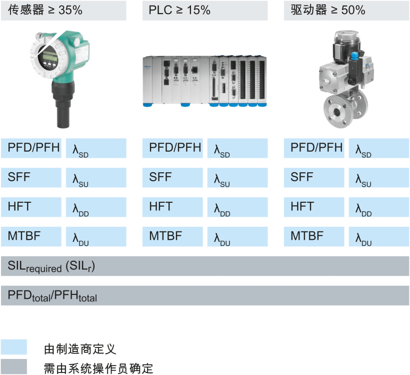
- λ(故障率),此处适用以下赋值原则:S 代表安全故障总比率;SD 代表安全故障、检测故障比率;SU 代表安全故障、未检测故障比率;D 代表危险故障总比率;DD 代表危险故障、检测故障比率;DU 代表危险故障、未检测故障比率。
- 设备类型:A 是所有元件的故障行为和故障特征都已充分确定(例如,通过已验证的性能)的设备代码。而设备类型 B 指至少一个元件的故障行为和故障情况下的行为没有得到充分确定。
- HFT(硬件故障裕度):在出现故障和偏差时继续执行所需功能的能力。HFT0:单个故障可能导致安全功能丧失(例如,在 1oo1 回路中)。HFT1:只有当至少两个故障同时发生时,才会发生安全功能丧失(例如,在 1oo2 回路中)。HFT2:必须同时发生至少三个故障(例如,1oo3 回路)。
- 高需求:安全系统激活需求频率高或有持续需求的运行模式。它持续运行或需要每年激活安全系统一次以上。
- 低需求:安全系统激活需求频率低的运行模式。它不得一年激活一次以上。
- MTBF(平均故障间隔时间):两次连续故障之间的平均时间。
- PFD(按需故障概率):安全功能在低需求模式下出现故障的概率(需求率/年 < 10)=低需求。
- PFH(每小时故障概率):安全功能在连续使用期间内出现故障的概率(需求率/年 > 10)=高需求。
- SFF(安全故障率):安全故障占故障总数的比例。
安全系统由什么组成?
SIL 回路通常由三个部分组成:
- 传感器(如压力传感器、温度传感器和液位计)
- 电子信号值比较和输出单元(如安全可编程逻辑控制器)
- 自动过程阀,包括空气电磁阀、驱动器和过程阀。
什么是 PFD/PFH 分布?
对于单通道系统,故障概率在安全功能子系统中的分布如下:驱动器的 SD 故障率被赋予最大权重。

在哪里可以找到这些值?
SIL 计算所需的所有故障概率可以在制造商的声明或证书中找到(以蓝色突出显示)。它们用于根据 SIL 计算总故障概率(以灰色突出显示的值)。

什么时候需要证书?
工厂要求的安全等级越高,SIL 标准对功能安全评估机构的独立性级别要求就越高。根据 IEC 61511,制造商的声明足以符合 SIL2 的要求。 对于 SIL3 以上等级的设备,必须是由独立机构颁发的证书。
安全整体性等级——评估机构
SIL1——独立个人
SIL2——独立部门
SIL3——独立组织
SIL4——独立组织
SIL 证书在哪里?
Festo 产品的 SIL 证书和 SIL 制造商声明可在“下载和媒体”中“证书”类别下相应产品详情页面中找到。
如何能够实现对驱动器的冗余控制?

有哪些 SIL 冗余解决方案?

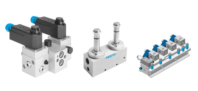
Festo 针对每种安全要求都有合适的冗余驱动器:
冗余 NAMUR 阀组(1oo2、2oo2):NAMUR 阀组允许安装两个带有 NAMUR 孔型的电磁阀,它们通过 NAMUR 接口进行冗余接线。这些阀组可具有故障保护功能 (1oo2) 或更高可用性 (2oo2)。您可以通过接口将阀组直接安装在角行程驱动器上。也可以使用合适的管道进行单独安装。
冗余管式气控阀(1oo2、2oo2):在这些紧凑式系统中,Festo 正在应用久经考验的 VOFD 阀技术。气控阀的冗余回路可确保冗余故障保护功能 (1oo2) 或为自动化过程阀提供更高的可用性 (2oo2)。得益于 Ematal 涂层,这些气控阀符合过程工程中的最高安全标准,并能承受最恶劣的环境条件。
混合阀组 (2oo3):2oo3 系统结合了两种技术,因此提供了最高等级的安全性和可用性。这种阀组是一种集成到您工厂的管式派生型。根据 VDI/VDE 3845,已安装的标准阀通过 NAMUR 接口进行定义并安装在阀组上。这意味着阀组一旦安装,便只需根据使用寿命/安全生命周期规划通过接口更换气控阀。此外,利用该系统,四个气控阀的功能可借助旁路实现,以便在运行期间进行维护。在气控阀受压的情况下,直接安装在阀组上的压力表始终能给出可靠和快速的指示。
谁需要了解这些安全知识?
咨询专家,了解 Festo 可以为您提供的服务。分享这个我们推荐的解决方案和示例应用的链接。